
Published: September 30, 2026 • Last updated: September 30, 2026
By Thomas Reynolds, Pump Systems Engineer
Thomas has installed and serviced more than 1,000 residential well pump systems across the western US, specializing in submersible, jet, and transfer pumps.
If your well pump is tripping the breaker, running constantly, or simply refusing to start, the problem is very often in the wiring. A well pump wiring diagram shows you exactly how 120- or 240-volt house power flows through the pressure switch, relay, capacitor, and into the motor, and once you can read one, most electrical faults become a five-minute diagnosis with a multimeter instead of a $400 service call. In this 2026 guide I break down the circuit for both above-ground jet (shallow well) pumps and deep-well submersible pumps, walk through the wiring step by step, and give you a side-by-side comparison table so you can match the diagram to the pump you actually have.
Disclosure: As an Amazon Associate, we earn from qualifying purchases on this page. Product selections are based on independent research and real well water data.
Key Insight
Every residential well pump circuit is the same four-part chain: house power → pressure switch → relay or contactor (and capacitor, on small motors) → pump motor. The pressure switch only decides when to open and close the circuit, so if the pump will not start, start at the switch and work toward the motor. If it starts and then dies, the suspect is the relay, the overload protector, or a failing run capacitor. Reading the wiring diagram as a circuit rather than a pile of wires is what turns a mystery into a checklist.
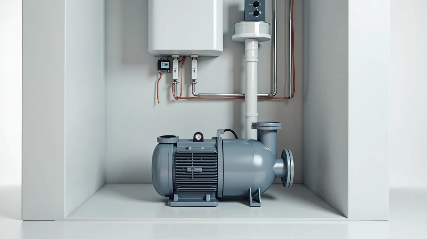
How a Well Pump Circuit Works
Strip away the brand-specific details and a residential well pump circuit is always the same four-part chain. House power leaves the breaker panel on a 120- or 240-volt branch circuit and travels through a cable to the pressure switch. The pressure switch is the only “smart” part of the circuit: it is a small mechanical valve-actuated contact that closes when tank pressure drops to the cut-in point (typically 30 PSI) and opens when pressure reaches cut-out (typically 50 PSI). When it closes, current flows through the relay (or a contactor on 240-volt and submersible systems), which in turn powers the pump motor. On small single-phase motors a run capacitor sits in the motor circuit to give the rotor its starting torque and improve efficiency.
Two different wiring philosophies follow from this. An above-ground jet or shallow-well pump sits next to the pressure tank in the basement or well house, so all four components are in one location and the wiring is a short loop you can trace with your hands. A deep-well submersible pump hangs 50 to 400 feet underground, so the pressure switch and relay stay in the house and the motor is powered through a dedicated pump cable that runs the full depth of the well. The same four-part logic applies; the cable just gets very long.
Figure 1. The four-part well pump circuit (jet / shallow-well system)
The pressure switch opens and closes the circuit based on tank pressure. The relay carries the full motor load current and includes an overload protector. The run capacitor (small motors only) boosts torque and efficiency. Arrow direction is conventional current flow under load.
The Four Key Components in the Circuit
Each component has a specific job and a specific failure mode. Knowing them is the whole game, because 90 percent of well pump electrical problems trace to one of these four parts.
1. Pressure switch
A snap-acting switch wired in series with the pump. It senses tank pressure through a small pipe connection and opens at cut-out, closes at cut-in. The most common wiring-related fault is a failed or leaking switch that lets the pump run continuously or prevents it from ever starting. If yours is acting up, our guide on how to adjust a well pressure switch covers cut-in/cut-out settings and how to test the contacts.
2. Relay and contactor
On 120-volt systems a small electromechanical relay (often built into the pump or the pressure switch assembly) handles the motor current. On 240-volt and submersible systems a heavier-duty contactor does the same job and is mounted in a pump panel. Both include an overload protector (a small thermal trip) that opens if the motor draws too much current. A relay with welded or pitted contacts is a classic cause of a pump that will not start even though the breaker is on.
3. Run capacitor
A single-phase induction motor needs a phase-shift to start and to keep running efficiently. On motors under roughly 3 HP that phase-shift comes from a run capacitor (and on some, a separate start capacitor). A weak or failed run capacitor makes a pump hum but not start, or start and then stall. Our companion piece, Well Pump Capacitor: How to Test, Choose and Replace, shows how to read the microfarad rating and swap a failed one safely.
4. Pump motor
The motor itself is the end of the line. On a submersible it is sealed in a stainless housing at the bottom of the well; on a jet pump it is the frame and windings you can see. Motor windings that are shorted or open will draw high amps and trip the breaker, or draw low amps and simply not turn. A clamp-on meter reading the motor current is the fastest way to separate a motor problem from a control problem.
How to Wire a Jet (Shallow Well) Pump
A jet or shallow-well pump is the easiest to wire because everything is in one spot. The pump usually ships with a 3- or 4-conductor pump cord that plugs into the pressure switch. Here is the standard 120-volt single-phase connection, in the order the wires actually carry the circuit.
- Turn the breaker off for the well pump circuit and verify with a multimeter that there is no voltage at the switch. Never work on an energized circuit.
- Land house power on the switch. Connect the 120-volt line (black/hot) and the neutral (white) to the pressure switch line terminals. The ground (green) bonds to the switch body and to the panel ground.
- Connect the pump cord load terminals. The pump cord plugs into the pressure switch load side. On a 3-conductor cord the hot, neutral, and ground map one-for-one; on a 4-conductor cord the extra conductor is the start-winding lead for the relay.
- Wire the relay (if separate). On pumps with an external relay, the pressure switch drives the relay coil and the relay contacts pass the motor current to the motor and capacitor. Match the coil voltage (typically 120V) to the supply.
- Connect the run capacitor to the motor terminal marked C (common) and the run winding terminal, per the motor nameplate diagram.
- Set the pressure switch to the correct cut-in/cut-out (commonly 30/50 PSI) and confirm the tank pre-charge is set about 2 PSI below cut-in.
- Restore power and test the start/stop cycle. The pump should start as the tank drops to cut-in and stop at cut-out, with no humming, no short-cycling, and no tripped breaker.
Pro Tip
On a 120-volt jet pump the pressure switch, relay, and capacitor are often a single pre-wired assembly on top of the pump. If you are replacing one, photograph the existing connections before you unplug anything and match the new unit to the same terminal layout. The pump nameplate almost always carries a small wiring diagram for the capacitor and relay connections, so use it as your reference instead of guessing.
How to Wire a Submersible Well Pump
A submersible pump is wired the same way in principle, but the long pump cable and the dedicated pump panel change the details. The pump cable (typically 4-conductor for single-phase: 2 power, 1 neutral, 1 ground, plus a separate ground) runs from the motor at the bottom of the well up to the submersible pump panel in the house or well house.
- Turn off the dedicated breaker and lock it out. Submersible circuits are a dedicated 20-amp or higher branch, so confirm you are on the right one.
- Land the branch circuit in the pump panel. The 240-volt (or 120-volt) supply connects to the panel bus, and the panel ground bus bonds the equipment ground.
- Connect the pump cable through the contactor. The two power conductors of the pump cable pass through the contactor, which is the heavy-duty on/off switch. The neutral and the equipment ground connect to their respective panel buses without going through the contactor.
- Wire the pressure switch to the contactor coil. The pressure switch drives the contactor coil (a low-voltage control circuit), and the contactor then carries the full motor current. The switch itself only handles the small coil current, never the motor load.
- Set the contactor overload to the motor full-load amperage (FLA) shown on the pump nameplate. This is what protects the long cable from overcurrent.
- Verify the ground path from the panel to the pump housing and, if required by your local code, to a ground rod. A submersible motor is sealed and far from any breaker, so a solid ground is a real safety requirement, not an afterthought.
- Restore power and confirm rotation. A submersible that is reversed spins the wrong way and will not develop pressure; a momentary test at the panel (or a rotation test) catches this before the pump runs dry.
Watch Out
On submersible systems the contactor is doing the heavy lifting, so it must be rated for the motor FLA with a margin for inrush current. An undersized contactor on a long cable is the most common cause of a submersible that trips its overload or welds its contacts. If the pump keeps tripping, our guide on well pump tripping the breaker walks through the ten causes in order of likelihood.
Jet vs. Submersible Wiring Comparison
The table below lines up the two systems so you can match the diagram to the pump you actually have. The logic is identical; the hardware and the cable length are what differ.
| Feature | Jet / Shallow-Well Pump | Deep-Well Submersible |
|---|---|---|
| Typical voltage | 120V (some 240V) | 240V (most common), some 120V |
| Switch / relay | Pressure switch + small relay, often one assembly on the pump | Pressure switch drives a contactor in a dedicated pump panel |
| Capacitor | Run (and often start) capacitor on small motors | Run capacitor in motor housing (usually not user-serviceable) |
| Pump cable | Short 3-4 conductor pump cord | Long 4-conductor pump cable, full well depth, to pump panel |
| Overload protection | Breaker + relay overload | Breaker + contactor overload set to motor FLA |
| Most common fault | Failed run capacitor or pressure switch | Contactor contact or long-cable voltage drop |
Values shown are typical for single-phase residential systems. Always confirm voltage, amperage, and terminal layout against your specific pump nameplate and the local electrical code.
Common Wiring Problems and Fixes
Most electrical faults fall into one of four buckets. Work from the switch toward the motor, and use a multimeter to check voltage and continuity at each stage. Always de-energize the circuit before touching a wire.
Pump will not start at all
Check in this order: breaker tripped or off, pressure switch contacts open or corroded, relay/contactor coil dead or contacts welded, blown fuse in the control circuit, or a loose terminal. If there is voltage at the switch but none at the relay, the switch is the fault. If voltage reaches the relay but not the motor, the relay or contactor contacts are the fault. A dead run capacitor on a single-phase motor also presents as a no-start with a hum.
Pump hums but does not run
This is almost always a start/run capacitor problem on a single-phase motor, or a locked-rotor condition. The motor is getting power but cannot develop enough torque to break loose. Replace the run capacitor to the same microfarad rating and check that the impeller is free to turn (with the pump off and the motor unplugged, try to spin it by hand). If the motor is hot and smelling of burnt windings, stop and call an electrician.
Pump runs but trips the breaker
A high-amperage draw means a shorted winding, a seized impeller, a low supply voltage (long cable voltage drop on submersible systems), or an undersized breaker/contactor. Measure the motor current with a clamp-on meter and compare it to the nameplate FLA. If the draw is well above FLA, the motor or the cable is the problem, not the breaker.
Pump short-cycles (rapid on/off)
Short cycling is usually a pressure problem, not a wiring one, but a sticky pressure switch contact can mimic it. Confirm the tank pre-charge, look for a leaking check valve or air in the line, and test the switch contacts for chatter. If the switch is healthy, the cycling is mechanical, not electrical.
Where to buy the key parts
These are the parts that actually fix most well pump electrical problems, with the typical spec to look for. Amazon carries all of them; the links below take you to the relevant search so you can compare current pricing and ratings.
| Part | What to Look For | Typical Use |
|---|---|---|
| Well Pump Run Capacitor | Match the nameplate microfarad (uF) and 440VAC rating | Single-phase jet / shallow-well motors under 3 HP |
| Well Pump Pressure Switch | 30/50 PSI cut-in/out, 1/8 NPT port | Standard residential jet and shallow-well systems |
| Well Pump Contactor | Rated at or above motor FLA, 120V coil for 240V system | Submersible pump panel, 240V systems |
| Digital Multimeter | AC voltage + continuity; clamp-on for motor current | Diagnosing every stage of the circuit |
| Submersible Pump Panel | Pre-wired panel with contactor and overload, 20A | Houses the contactor for a deep-well submersible |
Match every part to your pump nameplate rating. A capacitor or contactor that is too small for the motor will fail under load; one that is far too large wastes money without improving reliability.
Electrical Safety Rules
Well pump circuits are 120- or 240-volt and the submersible motor is sealed far below ground, so these are not optional niceties.
- De-energize and lock out. Turn the breaker off and verify zero voltage with a multimeter before touching any wire. Treat a pump circuit as live until proven dead.
- Discharge the capacitor. A charged run capacitor can hold a dangerous voltage for minutes after power is cut. Short its terminals with an insulated screwdriver (through a high-resistance path) before handling it.
- Use the right wire gauge. Undersized wire on a long submersible cable causes voltage drop and heat. Size the cable to the motor FLA and the well depth; when in doubt, go up a gauge.
- Bond the grounds. The panel ground, the equipment ground, and (where code requires) a ground rod must all be bonded. A floating ground on a sealed submersible is a shock hazard with no easy way to find the fault.
- Know your limit. If the breaker trips repeatedly, the motor smells hot, or you see charring at a terminal, stop and call a licensed electrician. A well pump is worth less than the cost of a house fire or a serious shock.
See Also
🔹 Well Pump Capacitor 2026: How to Test, Choose and Replace
🔹 How to Adjust a Well Pressure Switch 2026: Settings Guide
🔹 Best Digital Multimeters for Well Electrical Work in 2026
Frequently Asked Questions
How do I know if my well pump wiring is the problem?
If the breaker is on but the pump does not start, or it hums without running, the fault is almost always electrical. Use a multimeter to confirm voltage reaches the pressure switch, then the relay/contactor, then the motor. Whichever stage loses voltage is your problem. If every stage has voltage and the motor still will not turn, the motor windings or a locked impeller are the cause, not the wiring.
Does a submersible pump need a separate capacitor?
Most sealed submersible motors have the run capacitor built into the motor housing and it is not user-serviceable. If the capacitor fails, the usual repair is replacing the motor or the whole pump. On an above-ground jet pump, by contrast, the run capacitor is an external part you can test and swap yourself.
Can I wire a 120-volt jet pump to 240 volts?
No. A motor is built for one voltage. Running a 120-volt pump on 240 volts will destroy the windings almost immediately, and running a 240-volt pump on 120 volts will make it overheat and fail. Match the supply to the nameplate, or have a pump that is actually rated for the voltage you have.
Why does my well pump trip the breaker only in winter?
Cold weather thickens the water and can cause the motor to draw slightly more current, and a marginal connection or a wire that has developed a small fault will show up under that extra load. A frozen suction line or a partially iced pump can also lock the impeller. Check for freezing first, then test the motor current; a pump that is healthy in summer but trips in winter usually has a wiring or freeze issue, not a normal motor problem.
Do I need a licensed electrician for well pump wiring?
In most jurisdictions any permanent 120- or 240-volt wiring, especially a dedicated branch circuit to a pump panel, must be done by or inspected by a licensed electrician, and the local electrical code governs wire size, grounding, and GFCI requirements. Swapping a like-for-like capacitor or pressure switch on an existing correctly wired system is generally a homeowner task, but any change to the branch circuit, the panel, or the grounding should involve a licensed professional.
The Bottom Line
A well pump wiring diagram is not a mystery, it is a four-part circuit: power, pressure switch, relay or contactor, and motor. Read it as a path, start at the switch and work toward the motor, and most electrical faults become a five-minute multimeter check rather than a service call. If your pump will not start, hum without running, or trips the breaker, the cause is almost always a failed run capacitor, a sticky pressure switch, or a worn relay/contactor contact. Get the voltage to each stage, swap the part that fails the check, and keep the grounds solid. If you see heat, smell burning, or the breaker trips repeatedly, stop and call a licensed electrician, because a well pump is never worth the cost of a shock or a fire.
#WellPump #WellPumpWiring #WiringDiagram #PressureSwitch #Contactor #RunCapacitor #JetPump #SubmersiblePump #WellMaintenance #WellOwner #PrivateWell #WaterWell #DIYWell #ElectricalSafety #WellTroubleshooting
Sources
- Manufacturer installation and wiring diagrams for residential jet, shallow-well, and submersible pump systems.
- National Electrical Code (NEC) guidance on dedicated branch circuits, wire sizing, and grounding for pump equipment.
- Field service records from residential well pump electrical repairs, 2015 to 2026.